Analysis of the oil circuit connection problem of the flow valve in the hydraulic system
1. The overflow throttle valve can only be connected to the oil inlet of the actuator
The pressure difference between the inlet and outlet of the throttle valve in the hydraulic cylinder relief throttle valve is balanced with the spring force acting on the relief valve spool. This spring is a weak spring. If the relief throttle valve is used to perform On the oil return road of the mechanism, its outlet must lead to the oil tank, that is, the spring cavity of the overflow throttle valve is connected to the oil tank. If the load decreases at this time, the inlet pressure of the overflow throttle valve will increase, and the pressure can easily overcome the spring. Force, so that the oil entering the relief throttle valve mainly flows back to the oil tank through the relief valve port in the relief throttle valve, and can no longer be controlled by the throttle valve.
2. Pay attention to the direction of the one-way throttle valve when connecting the pipeline (that is, the oil inlet and outlet).
3. The improper position of the speed regulating element in the throttling speed regulating circuit makes the oil temperature too high.
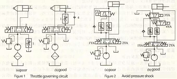
As shown in Figure 1(a), after working for a period of time, the oil temperature rises too high, which affects the normal operation of the system. The reasons are as follows.
① When the hydraulic cylinder 3 is in the stop position, the system is not unloaded, and all the pressure oil output by the pump flows back to the oil tank through the neutral position of the valve 2 and the valve 1, and the lost pressure can be converted into heat to increase the oil temperature.
②When the hydraulic cylinder 3 returns, the valve 2 is in the right position, and the return oil must also go through the valve 1 to return to the oil tank, and its throttling loss will increase the oil temperature.
This shows that when designing the outlet throttling speed regulating circuit, the position of the throttling speed regulating element should be set, and the system should be changed as shown in Figure 1(b), between the oil outlet of the hydraulic cylinder and the electromagnetic reversing valve Install the speed regulating valve, and add a check valve 4 to connect it in parallel with the speed regulating valve, so that the oil inlet path directly enters the rod cavity of the hydraulic cylinder through the check valve when fast reversing, so as to realize the fast rewinding action stroke and avoid oil leakage. The temperature rise is too high.
4. Instantaneous jump in the flow rate of the speed control valve leads to pressure shock
Figure 2(a) is the secondary feed circuit of a special machine tool hydraulic system. It realizes the action cycle of one work forward, one two work forward, one fast rewind and one stop. When the speed is switched from the first working to the second working, the hydraulic cylinder produces a large impact, which is caused by the jumping phenomenon of the flow rate when the pressure compensation mechanism of the speed control valve starts to work. A two-position three-way electromagnetic reversing valve is added to the circuit in Figure 2(b). It is not difficult to see that the speed control valve always has pressure oil passing through when the speed is switched, which avoids the occurrence of hydraulic shock.

5. The unreasonable structure of the flow valve makes it laborious to adjust the handwheel
The flow valve is under the action of the adjusting hand wheel and the return spring, so that the valve core moves in the valve body, thereby changing the size of the orifice and adjusting the flow. If the structure of the flow valve is unreasonable, resulting in oil leakage, orifice blockage, or spool jamming, the adjustment handwheel must overcome other resistances (including hydraulic pressure, friction, etc.), thus making the adjustment of the handwheel laborious.
6. If the cumulative error is not eliminated, the shunt valve is synchronized and the circuit is not synchronized
Due to the manufacturing error of the hydraulic cylinder bore, even when the flow rate of each branch is the same, the stroke of the cylinder also has an error, and the cumulative error of the long stroke cannot be eliminated, resulting in the synchronization of the diverter valve and the asynchrony of the circuit.
It is possible to rigidly connect multiple hydraulic cylinders mechanically, so that the hydraulic oil can be reasonably distributed and automatically adjusted through the diverter valve to achieve synchronization. This method is mainly used in occasions where the load is not too large.
Avoid the actual flow through the synchronous valve is too much less than its rated flow. When designing a synchronous valve (diverter valve), parameters such as its rated flow rate and relative diversion error are specified. The relative diversion error is inversely proportional to the square of the inlet flow rate of the synchronous valve. If the actual flow rate is too small, the relative diversion error will be greatly increased.
