Brief introduction of ordinary check valve and hydraulic control check valve
1.Ordinary check valve
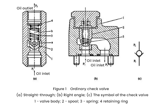
Ordinary one-way valve, referred to as one-way valve for short, is a valve that only allows oil to flow in the forward direction and does not allow reverse flow. According to the different flow directions of the oil in and out, it is divided into two structures: straight-through type (see Figure 1 (a)] and right-angle type [see Figure 1 (b)], which consists of a valve body, a valve core and a spring.
When the liquid flows in from the oil inlet P1, the oil pressure overcomes the spring resistance and the friction force between the valve body 1 and the valve core 2, and pushes away the valve core with a tapered end (when the flow rate is small, in order to simplify manufacturing, also A steel ball can be used as a spool), and it flows out from the oil outlet P2. When the liquid flow reversely flows from P2, the oil pressure makes the valve core tightly pressed on the valve seat, so it cannot flow backward. Figure 1(c) shows the symbol of the one-way valve.

The opening pressure of the one-way valve refers to the pressure difference between the inlet P1 and the outlet P2 when it is forward-conducting. In order to make the one-way valve sensitive and reliable, with small pressure loss and reliable sealing performance, the opening pressure should be appropriate, generally around 0.04MPa. When using the one-way valve as a back pressure valve, a spring with a higher rigidity should be replaced so that when it is forward-conducting, the opening pressure is relatively high, resulting in a certain back pressure, generally the back pressure is 0.2-0.6 MPa.
2. Hydraulic control check valve
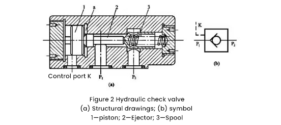
Figure 2 shows the hydraulic control check valve. It can be seen from the figure that the hydraulic control check valve has one more control oil port K, control piston 1 and ejector rod 2 than the ordinary check valve in structure.
When there is no pressure oil at the control oil port K, the hydraulic control check valve works the same as the ordinary check valve, that is, when the pressure oil enters from the P1 port, it can flow out from the P2 port. On the contrary, when pressure oil enters from P2 port, it cannot flow out from P1 port. When the control port K is filled with pressure oil, the left side of the control piston 1 is under the pressure, and the chamber a on the right side communicates with the oil drain port (not shown in the figure), the piston moves to the right, and the valve core 3 The top is opened, so that the oil port P2 communicates with P1, and the oil flow direction can be changed freely. It can be seen that the hydraulic control check valve has one more function than the ordinary check valve, that is, reverse controllable opening. The graphic symbol of the hydraulic control check valve is shown in Figure 2(b).

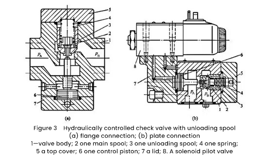
Figure 3 shows a hydraulically controlled check valve with an unloading spool, where the connection in Figure 3(a) is the flange type, and the connection in Figure 3(b) is the plate type with an electromagnetic pilot valve.
Take Figure 3(a) as an example to illustrate its working principle. Its main spool (poppet valve) 2 upper and lower ends have an axial small hole and 4 radial holes, and the axial small hole has a small unloading spool (poppet valve) 3 to close. When the high-pressure oil in chamber B needs to flow into chamber A in the reverse direction (generally the working condition after the pressure holding of the hydraulic cylinder is completed), when the control pressure oil pushes up the control piston 6, the control piston first pushes up the unloading spool The small distance makes the high-pressure oil in chamber B immediately flow out through the annular gap between the radial and axial holes of the spool and the lower end of the unloading spool, and the oil pressure in chamber B decreases. Realize pressure relief; then, the main spool is pushed open by the control piston, allowing the reverse oil to pass through smoothly. Due to the small control area of the unloading spool, only a small force can be used to push the unloading spool, thus greatly reducing the control pressure required for reverse opening. Its control pressure is only 5% of the working pressure, and the control pressure of the hydraulic control check valve without unloading spool is as high as 40% to 50% of the working pressure of T, so the hydraulic control check valve with unloading spool The valve is especially suitable for use in high-pressure and large-flow hydraulic systems.
The electromagnetic pilot valve 8 in Fig. 3(b) is fixed on the lower cover 7 of the one-way valve, which is used to control the on-off control of the pressure oil, which can simplify the oil circuit system and make the hydraulic system compact.

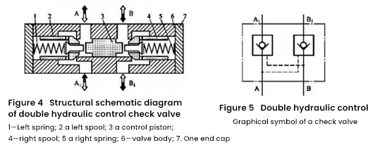
The double-hydraulic control one-way valve fork is called a two-way hydraulic lock. Figure 4 shows its structural schematic diagram, two hydraulically controlled one-way valves of the same structure share a valve body, and four oil holes A, A1 and B, B1 are provided on the valve body 7. When the liquid flow of one oil circuit of the hydraulic system enters the valve from chamber A in the forward direction, the pressure of the liquid flow automatically pushes the left valve core 2, so that chamber A communicates with A1, and the oil flows forward from chamber A to chamber A1. At the same time, the pressure of the liquid flow pushes the control piston 3 in the middle to the right, thereby opening the right valve core 4, making the B chamber communicate with the B1 chamber, and discharging the oil originally closed on the passage of the B chamber through the B chamber. On the contrary, when the liquid flow of one oil circuit of the hydraulic system enters the valve from the B cavity, the pressure of the liquid flow automatically pushes the right valve core 4, so that the B cavity communicates with the B1 cavity, and the oil flows forward from the B cavity to the B1 cavity . At the same time, the pressure of the liquid flow pushes the control piston 3 in the middle to the left, thereby opening the left valve core 2, making the A chamber communicate with A1, and discharging the oil originally closed on the passage of the A chamber through the A chamber. To sum up, the working principle of the dual-hydraulic control check valve is that when one oil chamber enters oil in the forward direction, the other oil chamber outputs oil in the reverse direction, and vice versa. And when there is no liquid flow in chamber A and chamber B, the reverse oil in chamber A1 and chamber B1 is closed under the tight contact between the cone surface of the valve core and the valve seat (hydraulic lock effect). Figure 5 shows the graphic symbol of the double hydraulic control check valve.

