Diagram of basic knowledge of relief valve
1.The structure of the relief valve
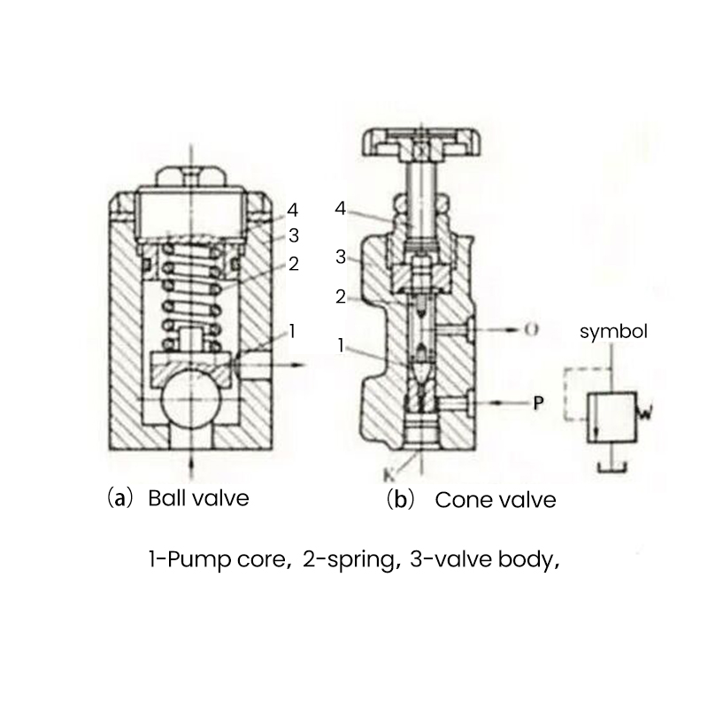
The structure of the overflow valve is shown in the figure. The overflow valve is mainly composed of a valve body, a valve core, a spring and an adjusting screw. In the figure (a) type is a spherical valve, (b) type is a cone valve. Ball valves are used in low-pressure, small-flow hydraulic systems; cone valves are used in higher-pressure and small-flow hydraulic systems, and the sealing effect of the spool of the cone valve is better than that of the ball valve. The structural composition of the overflow valve: 1--spool; 2--spring; 3--valve body; 4--screw.

2. The working principle of the overflow valve
When the relief valve works, it uses the pressure of the spring to adjust and control the pressure of the hydraulic oil. It can be seen from the figure that when the pressure of the hydraulic oil is lower than the working pressure, the spool is pressed against the inflow port of the hydraulic oil by the spring. When the pressure of the hydraulic oil exceeds the allowable pressure of the hydraulic oil, that is, it is greater than the spring pressure, the spool is lifted by the hydraulic oil, and the hydraulic oil flows in, flows out from the right port in the direction shown in the figure, and returns to the oil tank. The greater the pressure of the hydraulic oil, the higher the spool is lifted by the hydraulic oil, and the greater the flow of hydraulic oil flowing back to the oil tank through the relief valve. If the pressure of the hydraulic oil is less than or equal to the spring pressure, the spool will drop to seal the hydraulic oil inlet.
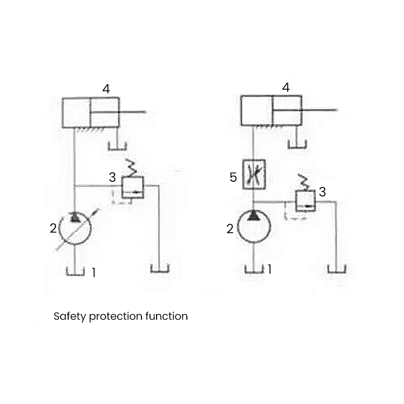
Since the pressure of the hydraulic oil output by the oil pump is fixed, and the pressure of the hydraulic oil used for the working cylinder is always lower than the pressure of the hydraulic oil output by the oil pump, some hydraulic oil will always flow back to the oil tank from the overflow valve during normal operation to keep the working pressure of the hydraulic cylinder balanced and working normally. It can be seen that the function of the relief valve is to prevent the hydraulic oil pressure in the hydraulic system from exceeding the rated load and play a role of safety protection. In addition, the overflow valve cooperates with the throttle valve, and the throttle valve adjusts the flow rate of hydraulic oil to control the moving speed of the piston. As shown below.

3.Types of Relief Valves
According to different structures, relief valves can be divided into two types: direct-acting and pilot-operated. The direct-acting relief valve is a relief valve in which the hydraulic pressure of the main oil circuit acting on the spool is directly balanced with the force of the pressure regulating spring. According to the different structures of the valve port and the pressure measuring surface, three basic structures are formed. Regardless of the structure, the direct-acting relief valve is composed of three parts: a pressure regulating spring, a pressure regulating handle, an overflow port and a pressure measuring surface. Comparison of direct-acting relief valve and pilot-operated relief valve: Direct-acting relief valve: simple structure, high sensitivity, but the pressure is greatly affected by the change of overflow flow, and the pressure regulation deviation is large. It is not suitable for working under high pressure and large flow.
Pilot-operated relief valve: The main valve spring is mainly used to overcome the friction of the valve core, and the spring stiffness is small. When the spring compression of the main valve changes due to the change of the overflow, the change of the spring force is small, so the change of the inlet pressure of the valve is also small. High pressure regulation precision, widely used in high pressure, large flow system. The spool of the relief valve is subject to friction during the movement process, and the direction of the friction force is just opposite when the valve port is opened and closed, so that the characteristics of the relief valve when it is opened are different from those when it is closed.
4. The main function of the overflow valve
Constant pressure overflow function: In the quantitative pump throttling regulation system, the quantitative pump provides a constant flow. As the system pressure increases, the flow demand decreases. At this time, the overflow valve is opened to make the excess flow overflow back to the oil tank, so as to ensure the inlet pressure of the overflow valve, that is, the outlet pressure of the pump is constant (the valve port is often opened with the pressure fluctuation).
Pressure stabilization function: The relief valve is connected in series on the oil return line, the relief valve generates back pressure, and the stability of the moving parts is increased.
System unloading function: The remote control port of the relief valve is connected in series with a solenoid valve with a small flow rate. When the electromagnet is energized, the remote control port of the relief valve is connected to the fuel tank, and the hydraulic pump is unloaded at this time. The relief valve is now used as an unloading valve.
Safety protection function: when the system is working normally, the valve is closed. Only when the load exceeds the specified limit (the system pressure exceeds the set pressure), the overflow is opened, and the overload protection is carried out to prevent the system pressure from increasing (usually the set pressure of the overflow valve is 10% to 20% higher than the maximum working pressure of the system).
In practical applications, it is generally used as an unloading valve, as a remote pressure regulating valve, as a high and low pressure multi-stage control valve, as a sequence valve, and used to generate back pressure (in series on the oil return line).
5. How to adjust the pressure of the hydraulic relief valve
Loosen all the screws of the relief valve, the equipment is running, slowly tighten the screws, watch the pressure gauge, stop after increasing the pressure by a few MPa, let the equipment run stably at this pressure for a few minutes, and then repeat the process of increasing the pressure and operating until it is adjusted to the set pressure.
There is a relief valve at the outlet of the oil pump of each hydraulic station. Sometimes, for some reason, the pressure at the outlet of the pump may be greater than the pressure required by the system. At this time, the relief valve is needed to relieve the excess pressure and drain the oil back to the tank.
6. Analysis of the reasons why the pressure of the relief valve rises but does not rise to the maximum
The phenomenon that the pressure of the relief valve rises but does not rise to the maximum regulating pressure is manifested as: even though the pressure regulating handwheel is fully tightened, the pressure can only rise to a certain value and then cannot continue to rise, especially when the oil temperature is high. The main reasons are as follows.
①The temperature of the hydraulic oil is high, and the internal leakage increases.
②The internal parts of the hydraulic pump are worn, the internal leakage increases, and the output flow decreases; the pressure rises, and the output flow is smaller, which cannot maintain the flow demand of high load, and the pressure rises below the maximum pressure. And it shows that after the pressure is adjusted, the pointer of the pressure gauge fluctuates violently, the fluctuation range is large, and the pressure of the relief valve cannot be adjusted.
③Larger dirt particles enter the damping hole or bypass hole of the main valve core, partially blocking the small hole, reducing the pilot flow into the pilot valve, making it difficult to build up a higher pressure in the upper cavity of the main valve core to balance the pressure in the lower cavity of the main valve core, so that the pressure cannot rise to the highest.
④ Due to the loose fit between the main valve core and the valve body hole, strain, grooves, or severe wear after use, part of the oil flow entering the spring chamber through the damping hole of the main valve flows through this gap to the oil return port (such as Y-type valves and two-section concentric valves).
⑤ The wear and tear between the pilot poppet valve and the valve seat is caused by dirt, water, air and other chemical substances in the hydraulic oil, which cannot be sealed well, and the pressure cannot rise to the highest level.
⑥ The contact surface between the pilot poppet valve and the valve seat has a gap. Or it is out of round and becomes jagged, so that the two cannot fit well.
⑦ The thread of the pressure regulating handwheel or the adjusting screw is bruised or strained, so that the pressure regulating handwheel cannot be tightened to the limit position, and the spring of the pilot valve cannot be completely compressed to the proper position, and the pressure cannot be adjusted to the maximum.
⑧The pressure-regulating spring becomes a soft spring due to wrong installation, or the rigidity decreases due to fatigue of the spring, or because it is broken, the pressure cannot be adjusted to the maximum.
⑨Because there are burrs, tapers or dirt on the main valve body hole or the outer circle of the main valve core, the main valve core is stuck at a small opening, and it is in a slightly open state of incomplete opening. At this point, although the pressure can be adjusted to a certain value, it cannot be raised any further.
