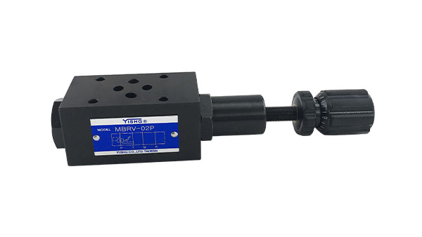
Simple classification of hydraulic valves
A hydraulic control valve is a component in a hydraulic system that controls the direction, pressure and flow of oil. With the help of these valves, the start, stop, direction, speed, action sequence and ability to overcome the load of the actuator can be controlled and adjusted, so that all kinds of hydraulic machinery can work in harmony as required. The following is a detailed introduction to the classification of hydraulic control valves:
Divided by use:
Hydraulic valves can be divided into directional control valves (such as one-way valves and reversing valves), pressure control valves (such as relief valves, pressure reducing valves and sequence valves, etc.) and flow control valves (such as throttle valves and speed control valves, etc.) ). These three types of valves can still be combined with each other as required to form a combined valve. Such as one-way sequence valve, one-way throttle valve, electromagnetic overflow valve, etc., which make it compact in structure, simple in connection, and improve efficiency.
According to working principle:
Hydraulic valves can be air switching valves (or on-off valves), servo valves, proportional valves and logic valves. After the on-off valve is set, it can only work in the set state. This chapter focuses on this most commonly used valve. Servo valves and proportional valves can control the data of the system continuously or proportionally according to the input signal. The logic valve controls the action of the actuator according to the pre-programmed logic program.
According to the form of installation and connection:
(1) Screw type (pipe type) installation connection. The oil port of the valve is connected with the pipe and other components with a screw pipe joint, and thus fixed on the pipe. This method is suitable for simple hydraulic systems.
(2) Screw-type installation connection. The oil ports of the valve are evenly arranged on the same installation surface, and are fixed on the connecting valve with the corresponding oil port with the valve, and then connected with other components with pipe joints and pipes; or these valves are fixed with screws on a On different sides of the manifold, holes are drilled on the manifold to communicate with each valve to form a circuit. Since there is no need to disassemble other connected components when disassembling the valve, this installation and connection method is widely used.
(3) Superimposed installation connection. The upper and lower sides of the valve are connecting joint surfaces, and the oil ports are respectively located on these two surfaces, and the oil port connection dimensions of the valve with the same specification are the same. In addition to its own function, each valve also acts as an oil channel. The valves are stacked to form a circuit without pipeline connection, so the structure is compact and the resistance loss is small.
(4) Flange installation connection. Similar to the screw connection, except that the flange type replaces the screw pipe joint. For large flow systems with a diameter of 32 or more. It has high strength and reliable connection.
(5) Cartridge installation connection, this type of valve does not have a separate valve body, the unit body consisting of the valve core, valve sleeve, etc. is inserted into the prefabricated hole of the cartridge block, fixed with connecting screws or cover plates, and passed The channel in the block connects the plug-in valves to form a circuit, and the plug-in block plays the role of the valve body and the pipeline. This is a new installation and connection method developed to adapt to the integration of hydraulic systems.

