Working principle of vane pump and vane motor
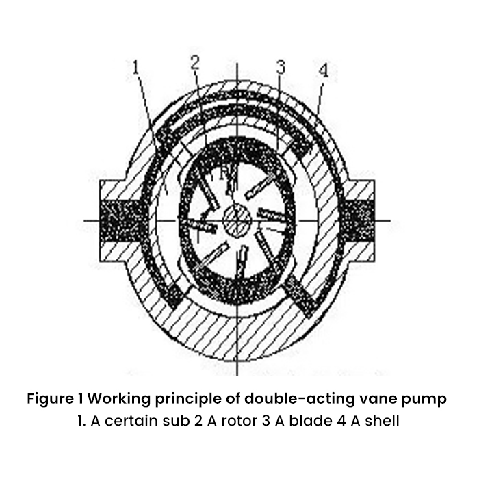
1.The working principle diagram of the double-acting vane pump is as follows:

2.Structural features
(1)The rotor and the stator are concentric, which is a quantitative pump;
(2)The inner surface of the stator is composed of two large arcs, two small arcs and four transition curves. The shape and nature of the transition curve between the large and small arcs determines the motion state of the blades, which has a great influence on the performance and life of the pump;
(3)There are two oil pressure chambers and two oil suction chambers on the circumference, the radial hydraulic force of the rotor shaft and the bearing is basically balanced, so the output pressure can be increased, and the shaft can be made thinner because it is not affected by the bending moment;
(4)The inclination angle of the blade installation, the inclination direction of the blade is at an inclination angle to the radial direction of the rotor. The inclination direction is different from that of the single-acting vane pump and is inclined forward along the direction of rotation. The purpose is to reduce the pressure angle between the blade and the stator and improve the force on the blade Condition;
(5)Prevent trapped oil phenomenon
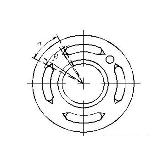
In terms of structure, it is necessary to ensure that the oil suction chamber and the pressure oil chamber do not communicate with each other, so there will be a dead volume during operation. In theory, the closed dead volume of the double-acting vane pump does not change and does not cause oil trapping, but in fact, considering the thickness of the vane, there will be oil trapping. For this reason, a triangular groove is opened in the oil pressure window (as shown in Figure 2), as shown below Prevent the occurrence of trapped oil phenomenon.

3.Flow calculation (see relevant calculation information)
4. Measures to increase the pressure of double-acting vane pumps
Increasing the pressure of the double-acting vane pump is one aspect of improving the performance of the vane pump. In general double-acting vane pumps, in order to ensure the close contact between the vane and the inner surface of the stator, the bottom of the vane is the pressure oil chamber, but when the vane is in the oil suction chamber, the pressure of the oil pressure chamber acts on the bottom of the vane, and the oil suction chamber acts on the top. The pressure of the cavity, this pressure difference makes the vanes press against the inner surface of the stator with great force, which accelerates the wear of the inner surface of the stator and affects the life of the pump. For high-pressure pumps, this problem is even more prominent, so high-pressure vane pumps must take structural measures to reduce the force that the vanes press against the inner surface of the stator.
(1)Reduce the oil pressure acting on the bottom of the blade, and pass the oil in the pump pressure chamber to the bottom of the blade in the oil suction area through the damping groove or the built-in small pressure reducing valve, so that when the blade passes through the oil suction chamber, the blade is pressed against the stator The force on the inner surface will not be too large.
(2)Reduce the width of the bottom of the blade under the action of pressure oil
Special blade ejection and compression structures such as mother blade, column pin blade, double blade, stepped blade, and spring blade are used to reduce the effective area of the blade root under the oil discharge pressure, so as to reduce the hydraulic pressure for pushing the blade out. thrust.
Prevent oil trapping
In terms of structure, it is necessary to ensure that the oil suction chamber and the pressure oil chamber do not communicate with each other, so there will be a dead volume during operation. In theory, the closed dead volume of the double-acting vane pump does not change and does not cause oil trapping, but in fact, considering the blade thickness, there will be oil trapping. Therefore, there is a triangular groove in the oil pressure window to prevent oil trapping. produce.

Working principle of vane motor
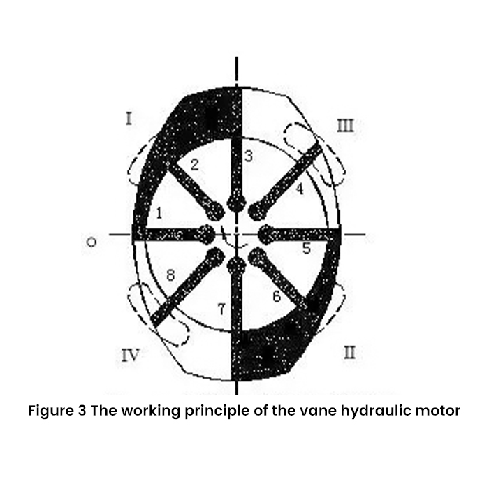
In the figure, I and II are oil inlet chambers, and III and IV are oil discharge chambers. When working, the high-pressure oil is introduced into I and II, and it is also introduced to the bottom of the blades, so that all the blades are pushed to the inner surface of the stator. Both sides of the blades (2, 6, 4, 8 in the figure) in the transition section of the stator surface are subjected to the same pressure, and no torque is generated. The blades 3, 7 and 1, 5 in the working section are subjected to high pressure on one side and low pressure on the other side, the protruding area of blade 3 is larger than that of blade 1, and the protruding area of blade 7 is larger than that of blade 5. out of the area. A clockwise torque is generated to make the rotor shaft rotate against the external load torque and output mechanical energy. Therefore, when III and IV enter oil and I and II return oil, the vane hydraulic motor produces counterclockwise torque. This is how the vane hydraulic motor works.
The vane motor needs to consider the starting problem. Generally, the following two solutions are adopted:
(1) A spring is added to the bottom of the groove of the blade to make the blade protrude to form a sealed working volume, but there is a problem of spring fatigue;
(2) Pass the oil twice, first pass oil to the bottom of the blade groove to push the blade out to form a sealed working volume, and then pass oil to the working volume. Vane motors can be used in frequent reversing situations.
