Fault Analysis and Troubleshooting of Throttle Valve in Hydraulic System
1. Throttle regulation failure
This failure phenomenon is manifested as; when the adjustment handle is adjusted, the outlet flow rate of the throttle valve does not change with the loosening or tightening of the handle, so that the movement speed of the actuator is maintained at a certain value (with the throttle valve core stuck It depends on the opening position), whether it should be fast or not, or slow or slow, or no matter how large the (handle) flow actuator is, it will not move, and no matter how small the throttle valve actuator is, it will still not slow down. This is the throttling adjustment failure. The causes and troubleshooting methods are as follows.
(1) Cause analysis.
①. The valve core is stuck or the throttle is blocked due to the dirt in the oil. The oil is very dirty, the working oil is aging, and the oil has not been finely filtered, so that the polluted oil passes through the throttle valve, and the polluted particles are wedged into the gap between the valve core and the valve body hole, and the same throttling adjustment failure phenomenon as above occurs. .
②. Because the gap between the valve core and the valve body hole is too small or too large, the valve core is stuck or the leakage is large, resulting in the failure of the throttling function.
③. There are scratches and scratches on the valve core and the inner and outer cylindrical surfaces of the valve hole, which make the valve core inflexible, or stuck, or have large internal leakage, resulting in loss of throttling.
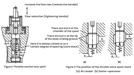
④. The throttle valve core is stuck due to burrs or the valve core is stuck due to the burrs at the sharp edge of the sinking groove of the valve body and the chamfer of the valve core, as shown in Figure 1. At this time, although the adjusting handle is released to drive the adjusting rod to move upward, the clamping force of the spool cannot be overcome by the force of the return spring, so the spool cannot be lifted up following the upward movement of the adjusting rod, as shown in Figure 2. When the spool is stuck at the position of closing the valve port, there is no flow output and the actuator does not move; when the spool is stuck at a certain opening position, there is only a small flow output, and the actuator only has a certain speed.

⑤. Due to the poor shape and position tolerance of the valve core and the valve hole, such as out-of-roundness and taper, hydraulic clamping is caused, resulting in throttling adjustment failure. At present, there is no pressure equalizing groove on the spool of the L-shaped throttle valve, which is prone to hydraulic clamping.
⑥. The equipment has been shut down for a long time and has not been used. The moisture in the oil has caused the valve core to rust and get stuck in the valve hole. When it is used again, the throttling adjustment failure occurs.
(2) troubleshooting.
①. When the oil is not clean, it is necessary to take measures to change the oil and strengthen the filtration. When the oil is changed, the oil must be changed in time.
②. Check whether the matching gap between the valve core and the valve body hole is suitable. If not, the valve hole can be ground for repair, or the valve core can be reconfigured.
If the valve hole is out of round or the matching clearance is too small, the valve hole can be ground for repair, or the valve core can be reconfigured.
③. Check the spool and the inner and outer cylindrical surfaces of the valve hole for scratches and scratches. The spool is slightly roughened and can be polished for reuse.
④. Use a nylon brush to remove the burrs in the valve hole, and the burrs on the valve core can be removed by manual finishing methods such as oil stone.
⑤. Check the shape and position tolerance of the measuring valve core and valve hole, and repair or replace it according to the situation.
⑥. For hydraulic equipment that has not been used for a long time, a comprehensive inspection should be carried out before re-use, and the hydraulic system should be changed and cleaned according to the situation.
2. Although the flow can be adjusted, the adjusted flow is unstable
This kind of failure phenomenon is manifested as: when the throttle valve is adjusted at a certain throttle opening and the adjusting screw is locked, the outlet flow rate is still changing, making the movement speed of the actuator appear sometimes fast, sometimes slow, and gradually slow down. Or the phenomenon of unstable speed such as gradual increase and sudden jump. Unstable flow will make the speed of the actuator unstable, especially when the lowest value of the flow adjustment range (minimum stable flow) and the pressure difference between the inlet and outlet of the throttle valve are the lowest working pressure value. The main causes of flow instability are "blockage" of the orifice, loose locking device, high oil temperature and large changes in load pressure, etc., as follows.
(1) Cause analysis.
①. Due to the blockage caused by the adsorption phenomenon of polarized molecules in the oil and the metal surface, the molecular chains in the oil will be charged and attracted to each other, so that one end will be positively charged and the other end will be negatively charged, and the molecular chain will become longer and longer. getting bigger. In addition, there is a potential difference on the metal surface, which will attract these polarized molecular chains, forming a solid boundary adsorption layer at the throttle gap and opening, and its thickness can reach 5-10um, which destroys the original geometry of the throttle gap. Shape and size, and for mineral oil, this adsorption layer is a gray fibrous layer tissue, which is periodically destroyed when it is under pressure, causing periodic pulsations in the flow.
②.Mechanical impurities mixed in the oil (such as dust, cutting dust, paint peeling flakes, etc.), as well as oil deterioration and aging products, will cause accumulation when passing through the throttling gap, block the throttling channel, and cause flow instability.
③. The oil temperature increases with the increase of the operating time of the hydraulic system, the oil viscosity decreases accordingly, and the flow through the throttling opening increases, but it may also decrease due to the increase of internal leakage, resulting in unstable flow.
④. The spool of the throttle valve adopts gap seal, and it can be seen from the flow formula of the annular gap that there must be internal leakage. When the fit gap increases due to wear, the internal leakage will also increase. And this internal leakage changes with various factors (such as oil temperature), thus affecting the stability of the flow, especially when the flow is small.
⑤. The external leakage of the throttle valve is large, resulting in unstable flow.

⑥. The oil has not been precisely filtered, and the impurities in the oil accumulate and adhere to the wall of the throttling channel, and the flow area is reduced, which slows down the speed of the actuator and completely blocks it, resulting in "broken flow"; the dirt is washed away, Then cause "jump".
⑦. When the pressure oil passes through the throttling gap, pressure loss will occur, the oil temperature will rise locally, the oil will be oxidized and deteriorated, and colloid, asphalt, carbon residue, etc. will be precipitated at the throttling port, which will adhere to the throttling port wall surface, causing The effective flow area is reduced or even blocked.
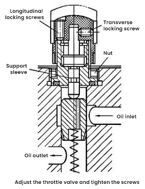
⑧. After the throttle valve is adjusted and locked, due to mechanical vibration or other reasons, the vertical and horizontal locking screws will be loosened (as shown in Figure 3), and then the adjusting rod will rotate and loosen on the support sleeve, so that the opening of the throttle valve The degree changes, causing the flow to change.
⑨. Air is mixed into the system, which greatly increases the compressibility of the oil, sometimes compresses, sometimes releases, and the flow is unstable.
⑩. The system load changes greatly, resulting in changes in the working pressure of the hydraulic cylinder, and the throttle valve does not have a pressure feedback compensation device like the speed control valve, so the pressure difference flowing through the throttle valve will change, and the flow rate will also change.
(2) troubleshooting.
①. Some measures can be taken when designing the throttle valve, mainly using metal with small potential difference as the throttle valve. Experiments show that steel to steel is better than copper to copper, and aluminum is the worst. Therefore, the L-type and IF-type throttle valves are steel to cast iron, and the potential difference is small.
②. The oil should be filtered at ordinary times, and an oil filter can also be installed in front of the throttle valve to keep the oil clean and pay attention to changing the oil.
③. Take measures to reduce system heat generation, replace oil with high viscosity index, etc. If it is caused by internal leakage, targeted measures can be taken.
④. Ensure a reasonable matching gap between the throttle spool and the valve hole, and adjust the throttle valve and the locking screw too large or too small as shown in Figure 87.
⑤. Check the cause of leakage outside the throttle valve, and take targeted measures.
⑥. To fine filter the oil, an oil filter should be installed in front of the throttle valve to keep the oil clean. Clean the orifice and change the oil if necessary.
⑦. Clean the throttle port, find out the oil pollution, and take measures such as oil change.
⑧. To eliminate the vibration source of mechanical vibration, a throttle valve with a lock adjustment handle can be used.
⑨. Remove the air in the system.
⑩. For the phenomenon of fast and slow due to load changes, the throttle valve can be changed to a speed control valve.
